| Source: | https://ashw.io/blog/arm64-hypervisor-tutorial/1 |
|---|
Hello and welcome to my new tutorial series on writing a bare metal hypervisor for 64-bit Arm systems!
In this series we will cover the fundamentals of virtualization in the 64-bit Arm architecture and develop an accompanying hypervisor step-by-step, beginning with simple examples hosting trivial virtual machines and working up to hosting fully-fledged operating system kernels such as Linux. Topics discussed will include device tree spoofing & stage 2 address translations, CPU feature spoofing & instruction emulation, device emulation, virtual interrupts, firmware interactions, and more.
The hypervisor code is being actively developed as an open source project on GitHub and will be demoed throughout the series on the Armv8-A Foundation Platform model as shipped with the freely available DS-5 Community Edition. Supplementary videos will also be hosted on my new YouTube channel.
This first post aims to introduce some key concepts and then kick-starts development with an example of how to boot a 64-bit Arm processor into a hypervisor and print “Hello, world!” over a PL011 UART serial console, all in A64 assembly.
First, take a step back and consider that the role of an operating system kernel is to:
provide layers of abstraction on top of the underlying hardware;
allocate and schedule resources between multiple user-space applications, including execution time, memory, file I/O, and access to peripherals;
In this way the kernel is said to supervise the user-space applications running on top of it. A hypervisor does exactly the same thing, but instead of hosting multiple user-space applications it hosts multiple operating system kernels; it supervises the supervisor, hence the name hypervisor.
A hypervisor creates virtual machines that behave as though they are real, physical machines; in certain use cases the operating system kernel controlling the virtual machine, referred to as a guest, truly believes it has control of a real, physical machine and has no idea it is being virtualized. However this typically comes with a performance penalty so in other use cases the guest is made aware that it is being virtualized and can then cooperate with the hypervisor to reduce overhead; this is known as para-virtualization.
Typical applications of virtualization include sandboxing certain processes & tasks or running a second operating system on a machine that is already running some other operating system, such as to test cross-platform software or to run a legacy application. Virtualization is a widely used tool and is the cornerstone of compute hosting services where one rents a virtual machine running in the cloud (think: Amazon Web Services and Microsoft Azure, to name but a few).
The industry defines two types of hypervisor, imaginatively named Type 1 and Type 2.
Type 1 hypervisors are also known as bare metal hypervisors as they sit directly on the hardware with no underlying host operating system. In contrast, Type 2 hypervisors are also known as hosted hypervisors as they either run on top of, or are themselves a part of, a host operating system running on the hardware:
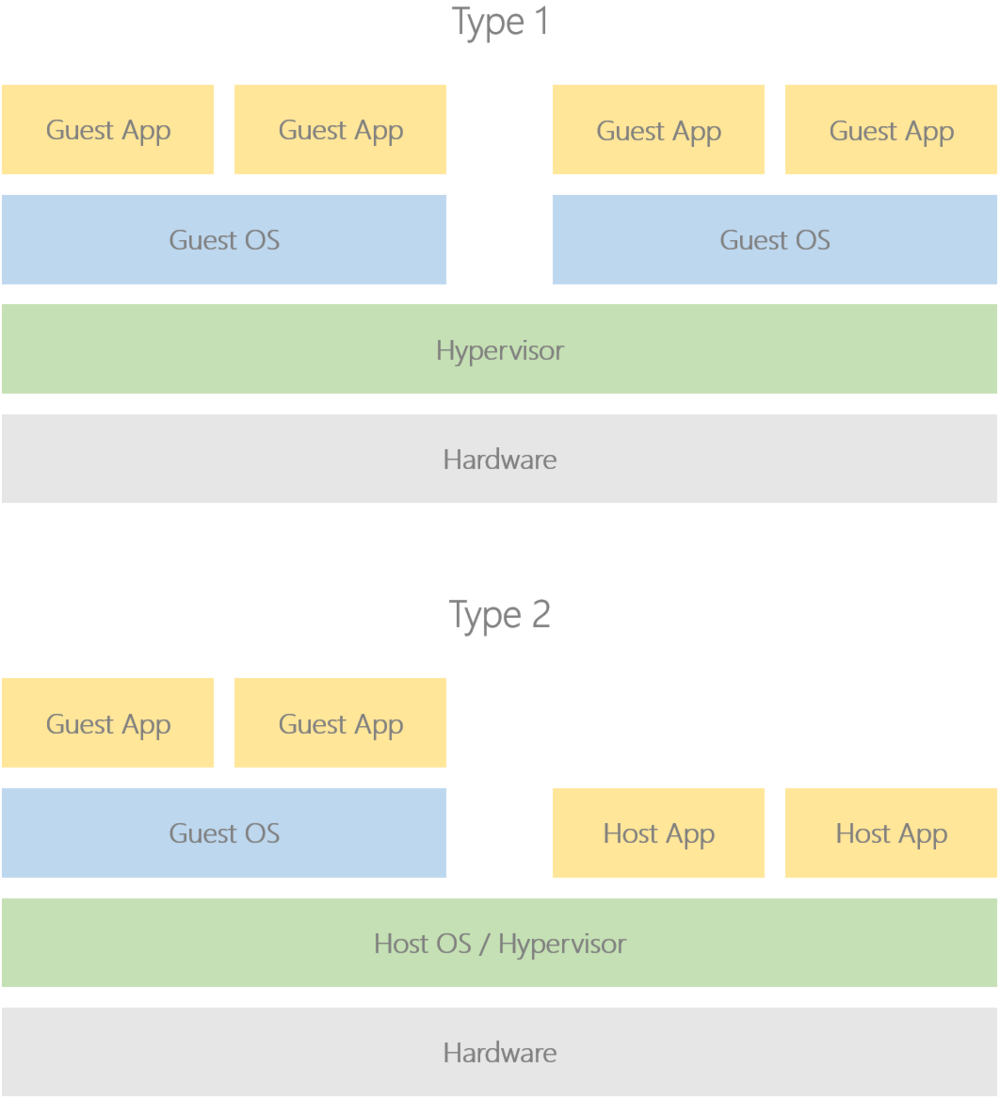
A well-known open source Type 1 hypervisor is Xen Project, and for Type 2 hypervisors take a look at Linux’s built-in Kernel-based Virtual Machine (KVM) solution. In this tutorial series we will be developing a Type 1 i.e. bare metal hypervisor.
To better understand this we should first take another look at operating system kernels, specifically the techniques they use to supervise user-space applications. with one of the best examples being virtual addressing.
Each time an application accesses a memory location, that access is made to a virtual address that is automatically translated to a physical address by the memory management unit (MMU) using page tables programmed by the kernel; these tables are also used to specify properties and attributes such as access permissions and whether the processor can execute from the region.
The kernel can use the page tables to present a fake view of the system to user-space applications, such as by making each application believe it running at the bottom of memory and making non-contiguous blocks of physical memory appear as a single contiguous block to an application.
For example, if a system has 2GB DRAM starting at address 0x8000_0000 (something you may see often on Arm systems; see this white paper [PDF]), then an application with a 64KB working set may have a view of memory that looks something like this:
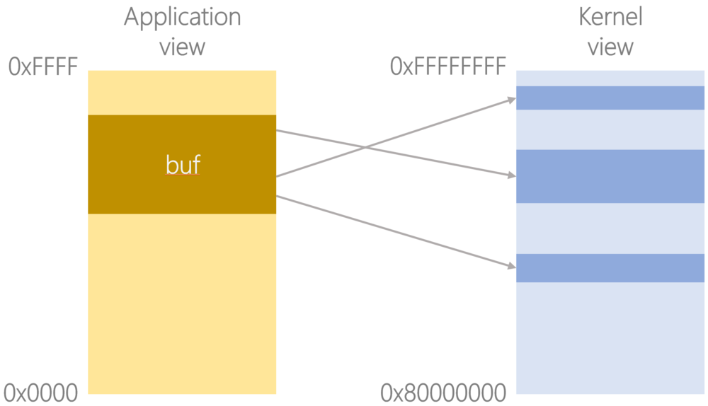
Note how the application has no idea where in physical memory it has actually been loaded, nor how much physical memory is actually available, nor that its malloc’d buffer is actually built up of non-contiguous blocks of physical memory; this is simply the view that is presented to the application, and it’s the kernel that has a view of the real, physical system.
At least, it thinks it does.
Enter the hypervisor, which controls a second set of page tables in the MMU, taking what the kernel thinks are physical addresses and translating them into real, physical addresses; the hypervisor can therefore present guest kernels with a view of the system that may not match the actual underlying hardware.
Expanding the figure above, the kernel believes the system has 2GB DRAM starting at physical address 0x8000_0000, but there could actually be 16GB available starting at physical address 0x10_0000_0000, and the 2GB visible to the kernel is simply a buffer that the hypervisor has allocated out of that 16GB. Further, the kernel’s contiguous 2GB chunk of DRAM may actually comprise a number of non-contiguous blocks in the real, physical system’s memory, just like the application’s malloc’d buffer was in the kernel’s view of memory.
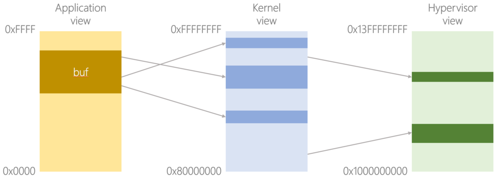
Architecturally, the kernel controls stage 1 translations mapping virtual addresses onto an intermediate physical address space, and the hypervisor controls stage 2 translations mapping these intermediate physical addresses onto the real, physical address space.
There are other tools available to the hypervisor, including trapping instructions and system register accesses, having visibility of physical interrupts before the guest (termed routing), injecting virtual interrupts into the guest, and more. These are used in conjunction with stage 2 translations to construct a virtual machine that a guest operating system kernel controls as though it is a real, physical machine.
Further, just like how an operating system kernel is able to context switch between multiple user-space applications, a hypervisor is able to context switch between multiple operating system kernels. Technically, the hypervisor schedules virtual cores on real, physical cores, and a single virtual machine may comprise many virtual cores; this also means we are able to run SMP operating systems on virtual machines.
The 64-bit Arm architecture defines the following levels of privilege:
EL0 for user-space applications;
EL1 for operating system kernels;
EL2 for the hypervisor;
EL3 for firmware, which also acts as gatekeeper to the Secure world (TrustZone);
Note: EL is short for Exception Level.
While this tutorial series primarily focuses on the interactions between EL1 and EL2, note that an Arm processor will always reset into the highest implemented exception level i.e. EL3 on the Armv8-A Foundation Model. This is important because the architecture only guarantees a bare minimum known safe state at reset:
the MMU and caches are disabled at the highest implemented exception level;
all asynchronous exceptions are masked at the highest implemented exception level;
And that’s pretty much it; most other system registers have architecturally UNKNOWN values at reset. This means we do not know:
whether EL2’s MMU and caches are enabled or disabled;
whether EL2 is 32-bit or 64-bit;
whether EL2 and below are Secure or Non-secure;
We will therefore need to configure these elements of the processor context before actually dropping to EL2, otherwise we risk performing an illegal exception return or immediately taking an MMU abort when trying to fetch the first instruction at the hypervisor entry point; given that EL2’s vector base address register VBAR_EL2 also has an UNKNOWN reset value, this MMU abort would likely throw us into a recursive exception upon trying to fetch the first instruction of the synchronous exception handler.
The entry3.S file shows how to perform this configuration before passing control to the hypervisor in EL2:
    globalfunc entry3
        // Install dummy vector table; each entry branches-to-self
        ADRP    x0, dummy_vectors
        MSR     VBAR_EL3, x0

        //
        // Configure SCR_EL3
        //
        //   10:10 RW       x1      make EL2 be 64-bit
        //   08:08 HCE      x1      enable HVC instructions
        //   05:04 RES1     x3      reserved
        //   00:00 NS       x1      switch to Normal world
        //
        MOV     w0, #0x531
        MSR     SCR_EL3, x0

        //
        // Configure SCTLR_EL2
        //
        //   29:28 RES1     x3      reserved
        //   23:22 RES1     x3      reserved
        //   18:18 RES1     x1      reserved
        //   16:16 RES1     x1      reserved
        //   12:12 I        x0      disable allocation of instrs into unified $s
        //   11:11 RES1     x1      reserved
        //   05:04 RES1     x3      reserved
        //   02:02 C        x0      disable allocation of data into data/unified $s
        //   00:00 M        x0      disable MMU
        //
        LDR     w0, =0x30C50830
        MSR     SCTLR_EL2, x0

        //
        // Prepare to drop to EL2h with all asynchronous exceptions masked
        //
        //   09:09 D        x1      Mask debug exceptions
        //   08:08 A        x1      Mask SErrors
        //   07:07 I        x1      Mask IRQs
        //   06:06 F        x1      Mask FIQs
        //   04:04 M[4]     x0      Bits 03:00 define an AArch64 state
        //   03:00 M[3:0]   x9      EL2h
        //
        MOV     w0, #0x3C9
        MSR     SPSR_EL3, x0

        // Drop to hypervisor code
        ADR     x0, entry2
        MSR     ELR_EL3, x0
        ERET
    endfunc entry3
The globalfunc and endfunc here are convenience macros defined in asm.h that together:
place the function in its own executable section;
define a symbol at the start of that section, marked as a function;
export the symbol to have global scope;
insert debugging info into the assembled binary, including function start, function end, and symbol size;
You’ll also notice we installed a dummy vector table at EL3. In the 64-bit Arm architecture, each entry in the vector table is 32 instructions long and the entry that is branched to is determined by both the type of the exception and from where the exception was taken:
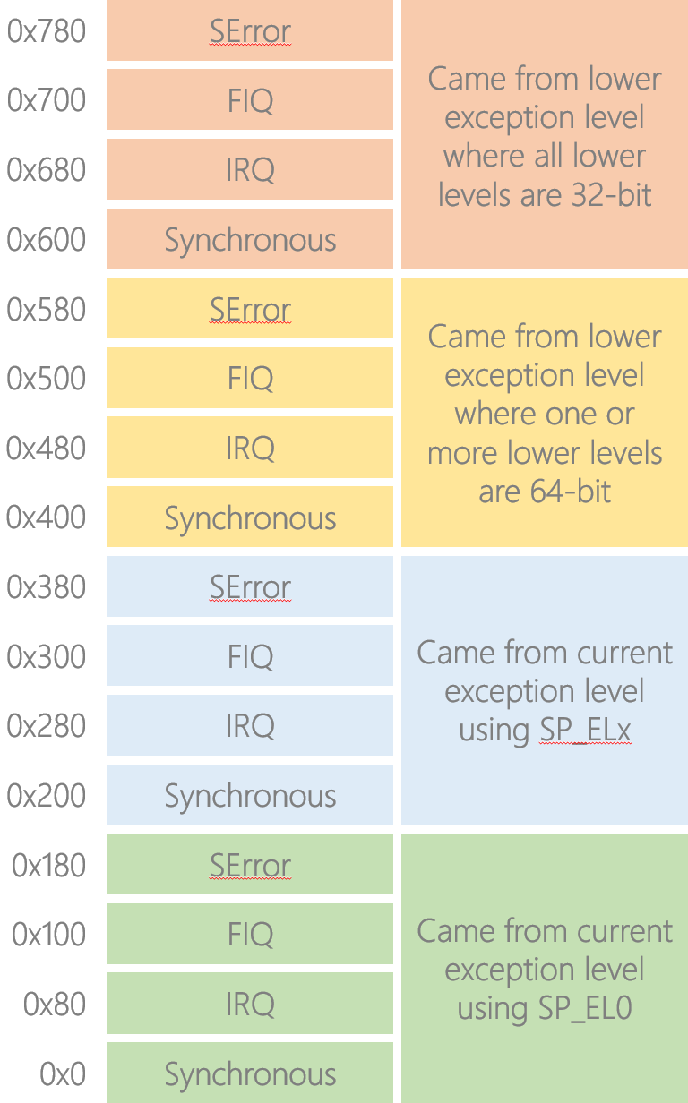
Regarding the green and blue blocks, the architecture gives EL1, EL2, and EL3 the ability to switch between two stack pointers: SP_EL0 and SP_ELx e.g. SP_EL2 for EL2. Privileged software uses this to switch between thread mode (SP_EL0) and handler mode (SP_ELx). Note that when privileged software is in thread mode i.e. using SP_EL0, it’s not actually using the user-space stack; rather, the user-space stack pointer will have been saved off as part of the application’s context and the register value overwritten with the privileged software’s thread mode stack pointer.
What would happen if the vector table did not differentiate between exceptions taken using SP_EL0 and exceptions taken using SP_ELx, and privileged software then took a stack overflow?— Exercise for the reader
The yellow and pink blocks are used to determine how much effort needs to be expended in context switching out the less privileged software. Note in the yellow block we say “one or more lower levels are 64-bit”; this is strictly different to saying that we came from a 64-bit level.
Consider a 64-bit hypervisor at EL2 hosting a 64-bit guest kernel at EL1, which is in turn hosting a 32-bit user-space application at EL0. Let’s say we are currently running in the application code and take a hypervisor scheduler tick interrupt to EL2; we’ll need to perform a full 64-bit context switch even though we came from a 32-bit context, so in this example we’d have taken the exception to the yellow vector block. In contrast, if the guest kernel itself was 32-bit then we’d have taken the exception to the pink vector block.
We refer to the vector table installed here as a “dummy” because each entry is just a branch-to-self instruction; this is useful early on in development before we have written a proper vector table, and for early on in the boot process before we are actually ready to handle exceptions. Even though we’re not going to be doing anything in EL3, it’s good practice to install a dummy vector table so that any exceptions result in safely spinning and we can use a debugger to read out the syndrome registers to figure out what went wrong; otherwise we’d instead get thrown into a recursive exception and the syndrome register will be trampled.
The hypervisor entry point in EL2 is defined in entry2.S:
    .data
    hello_world:
        .ascii "Hello, world!\0"


    globalfunc entry2
        ADRP    x0, dummy_vectors
        MSR     VBAR_EL2, x0
        ADRP    x0, _stack_start
        MOV     sp, x0
        BL      pl011_init
        ADR     x0, hello_world
        BL      pl011_puts
        B       .
    endfunc entry2
Here we also install another dummy vector table, initialise the stack pointer, enable the model’s PL011 UART, then print “Hello, world!” over it.
The PL011 driver functions are in pl011.S, and the keen-eyed among you may notice that pl011_init() doesn’t do a full initialisation; this is because the UART is not fully modelled on the Armv8-A Foundation Platform and is instead piped in/out over a local Telnet connection, so we don’t need to worry about setting the word length or baud rate and can instead just clear any flags and enable the UART:
    /*
    * Initialise the PL011 UART with Tx and Rx enabled.
    */
    globalfunc pl011_init
        LDR     x0, =PLATFORM_PL011_BASE
        STR     wzr, [x0, #CR]
        STR     wzr, [x0, #ECR]
        STR     wzr, [x0, #DR]
        LDR     w1, =0x301
        STR     w1, [x0, #CR]
        RET
    endfunc pl011_init
PLATFORM_PL011_BASE is defined as 0x1C09_0000 in platform.h, matching the base address of the PL011 UART on the Armv8-A Foundation Model; you can find the full system memory map here.
We use simple polled I/O to print a single ASCII character over the PL011 UART, and if the character is a newline ‘\n’ then we first print ‘\r’:
    globalfunc pl011_putc
        LDR     x1, =PLATFORM_PL011_BASE
        .macro wait_for_tx_ready
            1:
                LDR     w2, [x1, #FR]
                MOV     w3, #(FR_TXFF | FR_BUSY)
                AND     w2, w2, w3
                CBNZ    w2, 1b
        .endm
        wait_for_tx_ready
        CMP     w0, #ASCII_NL
        B.NE    2f
        MOV     w2, #ASCII_CR
        STR     w2, [x1, #DR]
        wait_for_tx_ready
    2:
        STR     w0, [x1, #DR]
        RET
    endfunc pl011_putc
Note that this function is not thread-safe, but that’s OK at this stage.
The GNU gas assembly syntax allows for special reusable numeric labels that can be referenced using b for first occurrence searching backwards or f for first occurrence searching forwards; for example, CBNZ w2, 1b means “conditionally branch backwards to the closest 1 label if w2 is non-zero”, while B.NE 2f means “conditionally branch forwards to closest 2 label if the ALU flags condition code NE (Not Equal) is true”.
To print an ASCII string we simply print each individual character using pl011_putc() until reaching a null character:
    globalfunc pl011_puts
        push    x20, x30
        MOV     x20, x0
    1:
        LDRB    w0, [x20], #1
        CBZ     w0, 2f
        BL      pl011_putc
        B       1b
    2:
        pop     x20, x30
        RET
    endfunc pl011_puts
Note the use of push and pop here, which are convenience macros defined in asm.h like globalfunc and endfunc; while previous versions of the Arm architecture had native PUSH and POP instructions based on LDM and STM (Load/Store Multiple), these instructions were removed in 64-bit Armv8-A and need to be constructed manually using regular loads and stores, or the new LDP and STP (Load/Store Pair) instructions:
    /* Stack 1-2 registers. */
    .macro push reg1:req, reg2:vararg
        .ifnb reg2
            STP     \reg1, \reg2, [sp, #-16]!
        .else
            STP     \reg1, xzr, [sp, #-16]!
        .endif
    .endm


    /* Pop 1-2 registers. */
    .macro pop reg1:req, reg2:vararg
        .ifnb reg2
            LDP     \reg1, \reg2, [sp], #16
        .else
            LDP     \reg1, xzr, [sp], #16
        .endif
    .endm
These macros ensure the stack pointer is kept 16-byte aligned even if less than 16 bytes are being pushed onto the stack; this is a requirement of the 64-bit Arm Procedure Call Standard [PDF].
That same document defines register conventions such as x30 being the link register, as well as which registers must be preserved between function calls and which can be trampled over by the callee. In the case of pl011_puts() we need to preserve the pointer to the next ASCII character between calls to pl011_putc(), so we put it in callee-saved register x20. However, the code that called pl011_puts() may itself have put something in x20 that it needs preserving, hence we stack it then restore it before returning at the end of the function. We also need to stack x30 as our return address will be trampled by the calls to pl011_putc().
In the hypervisor entry point function, entry2, we initialised the stack pointer to the address of _stack_start; this symbol is exported by the linker.ld script:
    ENTRY(entry3)

    SECTIONS
    {
        . = 0x80000000;

        .stack (NOLOAD): {
            . = ALIGN(16);
            _stack_end = .;
            . = . + (16 * 1024);
            . = ALIGN(16);
            _stack_start = .;
        }

        .text : {
            out/entry3.o(.text);
            out/entry2.o(.text);
            *(.text);
        }

        .data : { *(.data) }
        .bss  : { *(.bss) }
    }
The stack is always full descending in the 64-bit Arm architecture:
“full”, meaning the stack pointer points to the most recently pushed item, unlike an “empty” stack where it points to the next empty address;
“descending”, meaning the stack pointer is decremented when pushing an item, unlike an “ascending” stack where it is incremented;
DRAM begins at 0x8000_0000 on the model, so for now we place a single 16KB stack there, followed by the traditional text, data, and bss sections.
You’ll notice that the linker script also defines entry3 as the image entry point, corresponding to the minimal setup code in EL3.
The hypervisor source code is available as an open source project on GitHub, with the part-01 tag corresponding to the examples shown in this particular article.
To build the project we will use the bare metal (aarch64-elf) Linaro GCC 6.1-2016.08 cross compiler, available here.
    # Build project
    $ make all CROSS_COMPILE="/path/to/aarch64-elf-gcc/bin/aarch64-elf-"

    # Clean project
    $ make clean CROSS_COMPILE="/path/to/aarch64-elf-gcc/bin/aarch64-elf-"

    # Clean then build project
    $ make rebuild CROSS_COMPILE="/path/to/aarch64-elf-gcc/bin/aarch64-elf-"

    # You can also export CROSS_COMPILE to not have to pass it to make
$ export CROSS_COMPILE="/path/to/aarch64-elf-gcc/bin/aarch64-elf-"Throughout this series we will use the freely available Arm DS-5 Community Edition, which ships with the Armv8-A Foundation Model. This is a Fixed Virtual Platform (FVP) that allows us to easily run and debug our hypervisor code in real-time (you can even follow the instructions here to fetch, build, and run a fully-integrated software stack on the model, comprising firmware, boot loader, Linux kernel, and user-space filesystem. Disclaimer: I maintain these pages and the corresponding workspace initialisation script in my role as an Applications Engineer at Arm).
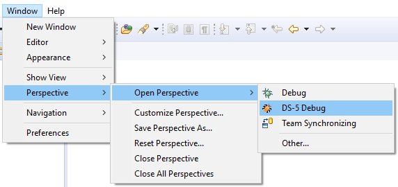
We will use the Eclipse for DS-5 Debugger to launch the model, load the hypervisor, then step through the code. First launch Arm DS-5 Community Edition, then switch to the DS-5 Debug perspective:
Navigate to Run > Debug Configurations… then select DS-5 Debugger and click New launch configuration.
On the Connection tab, select ARM Model > ARMv8-Ax1 Foundation Platform > Bare Metal Debug > Debug ARMv8-A
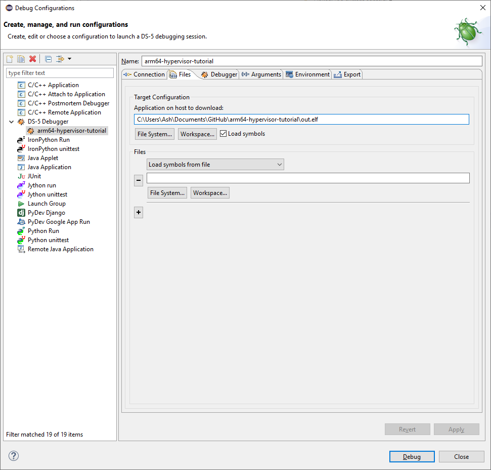
On the Files tab, in Application on host to download, navigate to the out.elf generated when you built the project, and ensure Load symbols is ticked
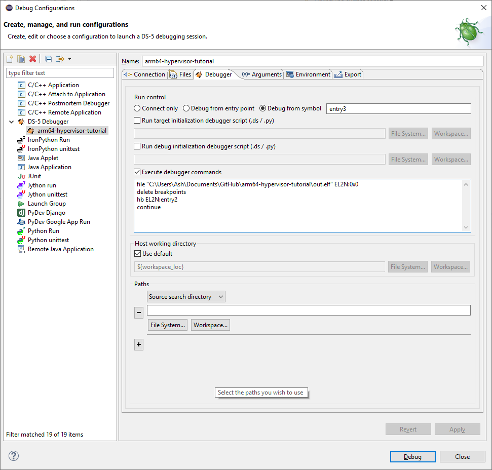
On the Debugger tab, select Debug from symbol and type entry3 into the box
While still on the Debugger tab, also tick Execute debugger commands then paste the following into the box, replacing /path/to/out.elf with the same path that you entered on the Files tab:
    file "/path/to/out.elf" EL2N:0x0
    delete breakpoints
    hb EL2N:entry2
    continue
These commands let us skip over the minimal setup code in EL3 and begin stepping through the code from the hypervisor entry point in EL2.
For reference, the screenshots below show the debug configuration that I created on my own machine:

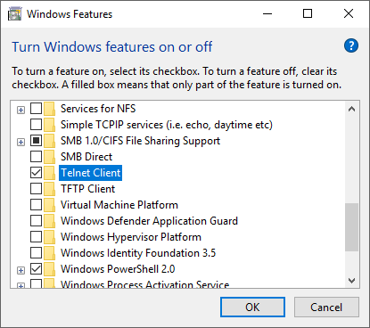
Before launching the model, make sure you have enabled the Telnet Client feature if running on Windows or have installed xterm if running on Linux.
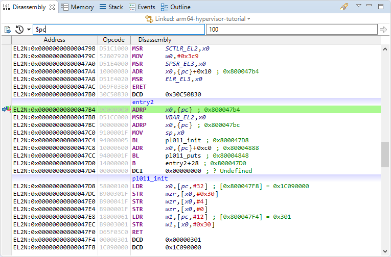
You can now launch the model and will be paused at the hypervisor entry point in EL2:
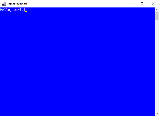
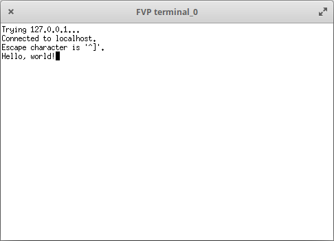
Resuming execution will open a Telnet or xterm window and print “Hello, world!”:
Thanks for reading, watch this space for part 2 of the tutorial series, coming soon!